Hampton Bay AC438-GM Gebrauchs- und Pflegehandbuch
Stöbern Sie online oder laden Sie Gebrauchs- und Pflegehandbuch nach Haushaltsfans Hampton Bay AC438-GM herunter. Hampton Bay AC438-GM Use and Care Manual Benutzerhandbuch
- Seite / 18
- Inhaltsverzeichnis
- LESEZEICHEN
- Garrison 1
- Ceiling Fan 1
- Owner’s Manual 1
- 52” Garrison 2
- Unpacking Your Fan 4
- Installing Your Fan 5
- Hanging the Fan 6
- Installing Fan to 7
- Making the Electrical 8
- Connections 8
- Finishing the Fan 9
- Installation 9
- Attaching the Fan Blades 10
- Blade Balancing 11
- Attaching the Switch 11
- Installing the 12
- Light Kit 12
- Fan without Light Kit 13
- Operating Your Transmitter 14
- PROBLEM SOLUTION 16
- Specifications 17
- Lifetime Limited Warranty 18
Inhaltsverzeichnis
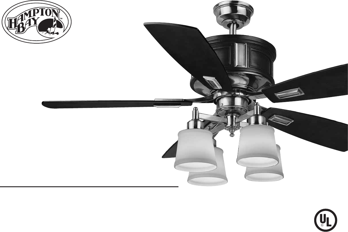
Garrison52 in Ceiling FanOwner’s Manual GarrisonVentilador de Techo de 1,32 mManual del Propietario 640 656
8Attaching the Fan BladesCAUTIONMOTOR IS SHIPPED WITH MOTOR SUPPORT PLATE PREVENT MOVEMENT DURING TRANS-PORTATION. REMOVE THE SCREWS FROM THE MOTOR SU
9Blade BalancingCheck that all blade and blade bracket screws are secure.Most fan wobble problems are caused when blade levels are unequal. Check this
10Installing the Light Kit.Remove the plug from the switch housing cover.(Fig. 18) Attach the light kit to the switch housing cover by feeding the lig
11Fan without Light Kit(Optional)Your fan is designed with light kit, in case you intend to install the fan without light kit. Attach the plastic plug
1212Installing the Battery:"HI, MED, LOW" buttons:These three buttons are used to set the fan speed as follows:LOW=Low speed, MED= Medium sp
13Speed settings for warm or cool weather depend on factors such as the room size, ceiling height, number of fans, and so on.The Reverse switch is loc
14WARNINGMAKE SURE THE POWER IS OFF AT THE ELECTRICAL PANEL BOX BEFORE YOU ATTEMPY ANY REPAIRS. REFER TO THE SECTION, “MAKING ELECTRICAL CONNECTIONS”.
15SpecificationsFAN SIZE SPEED VOLTS AMPS WATTS RPM CFM N.W. G.W. C.F.52” 12016.8 kgs(37 Ibs)19 kgs(41.8 Ibs)3.04’LOWMED.HIGH0.350.550.621540737012016
16The Hampton Bay warrants the fan motor to be free from defects in workmanship and material present at time of shipment from the factory for a period
52” GarrisonCeiling Fan by Hampton BayDate PurchasedStore PurchasedUL Model No.Serial No.Vendor No.UPCThank you for purchasing our ceiling fan. This p
Safety Rules - Read and Save These Instructions1To reduce the risk of electric shock, insure electricity has been turned off at the circuit breaker or
2Unpacking Your FanUnpack your fan and check the contents. You should have the following items:ABC127896 101415111213345Set of blades (5)Canopy assemb
3Installing Your FanTools RequiredMounting OptionsWARNINGTO REDUCE THE RISK OF FIRE, ELECTRIC SHOCK OR PERSONAL INJURY, MOUNT FAN ONLY TO AN OULET BOX
4Figure 5Motor WiresBall/Downrod AssemblyCeiling CanopyCanopy Bottom CoverPin in Locked PositioonMotor CollarCoupling CoverTighten Screw FirmlyREMEMBE
5Installing Fan to the Electrical BoxWARNINGTO REDUCE THE RISK OF FIRE, ELECTRIC SHOCK OR OTHER PERSONAL INJURY. MOUNT FAN ONLY TO AN OUTLET BOX OR SU
6Making the Electrical ConnectionsWARNINGTO AVOID POSSIBLE ELECTRICAL SHOCK, BE SURE ELECTRICITY IS TURNED OFF AT THE MAIN FUSE BOX BEFORE WIRING.(Fig
7Figure 12SUPPLY CIRCUITFigure 11Outlet BoxCeiling MountingBracketScrewsCanopyCanopyBottom CoverWHITEWHITEBLACKBLACKBLUEGroundConductorOutlet BoxGreen
Verwandte Produkte und Handbücher für Haushaltsfans Hampton Bay AC438-GM
 (18 Seiten)
(15 Seiten)
(15 Seiten)
(15 Seiten)
(18 Seiten)
(15 Seiten)
(15 Seiten)
(15 Seiten)
 (12 Seiten)
© 2020, manymanuals.de. Alle Rechte vorbehalten. | 2.488 s |
 Manymanuals.com
 Manymanuals.de
 Manymanuals.fr
 Manymanuals.it
 Manymanuals.pl
 Manymanuals.cz
 Manymanuals.es
 Manymanuals-pt.com
Kommentare zu diesen Handbüchern